DMA, short for Direct Memory Access, is a hardware mechanism that lets a device such as a network card, an NVMe drive, or an audio interface read and write system memory on its own, without the CPU copying every byte. The CPU sets the transfer up once, then gets an interrupt when the data has landed. That single change is why a modern machine can stream files at full speed while still running a dozen applications.
Searches for "what is DMA and how does it work" usually come from one of two places. Some are architecture students trying to make the 8237-era textbook diagram make sense. Others are developers or sysadmins who have hit a real problem, a driver that hands a device a buffer and then reads stale data, or a virtual machine that will not start because the IOMMU groups are wrong. Both groups get more out of this guide if you hold one picture in your head, which is the picture in the next section.
Table of Contents
- What Is DMA and How Does It Work?
- Why DMA Matters for Performance
- The Main Parts of a DMA Transfer
- What a scatter-gather descriptor is
- How a DMA Transfer Happens Step by Step
- DMA Types: bus mastering, scatter-gather, and cycle stealing
- Bus mastering
- Scatter-gather
- Cycle stealing
- Burst and transparent modes
- DMA Addressing and Transfer Modes
- DMA in Modern Systems
- DMA Security Risks and Protection
- How to Observe and Troubleshoot DMA
- Frequently Asked Questions
- What does DMA mean in OS?
- What is direct memory access?
- What is the structure of DMA?
- What are the disadvantages of DMA?
- Does DMA mean the CPU is completely bypassed?
- Should I disable DMA in my BIOS?
- Conclusion: Start with the Transfer Path
What Is DMA and How Does It Work?
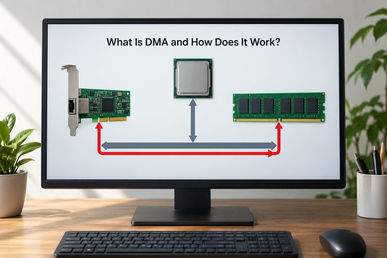
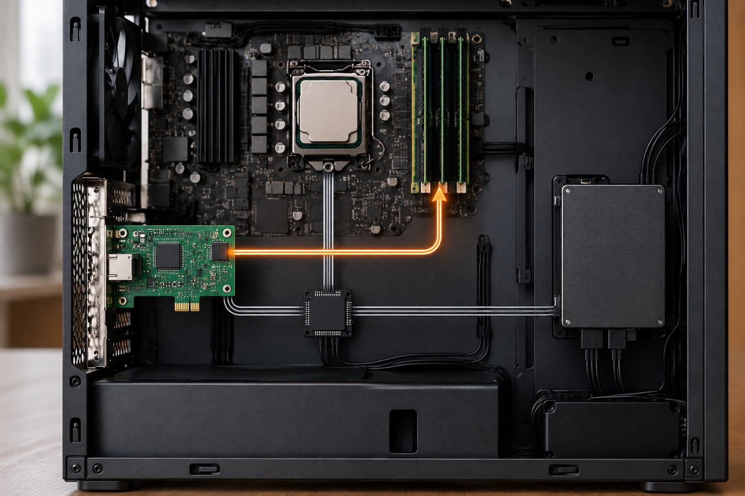
Here is the whole thing in one block. The CPU talks to the controller over registers. The controller talks to the device and to RAM over the system bus. Data never passes through a CPU register on its way from the device to memory.
  SETUP PATH (CPU programs the transfer)
  ---------------------------------------
  [ CPU ] --write to registers--> [ DMA controller / bus master ]
                                          |
  DATA PATH (controller moves the bytes)  |
  ------------------------------------    v
  [ Peripheral device ] <---bus---> [ DMA controller ] <---bus---> [ RAM ]
                                          |
  COMPLETION PATH                         v
  ------------------------------------  [ interrupt line ] --> [ CPU ]
The first important correction: DMA does not mean the CPU is bypassed. It means the CPU is uninvolved during the transfer itself. Before a single byte moves, the CPU, or more often the driver it is running, has to allocate a buffer, pin those pages in memory, program an address and a length into the engine, and arm it. Without that setup, the engine has no idea what to do.
Once armed, the controller arbitrates for the system bus the same way the CPU does. It wins a transfer cycle, moves one beat of data, and either gives the bus back or holds it for a burst. When the count reaches zero, the controller raises an interrupt and the CPU gets control back.
One thing worth stating plainly, because it trips up almost everyone: a DMA engine does no arithmetic. It does not parse headers, filter packets, or decompress anything. It moves words from one address to another. All the logic lives either in the CPU or in whatever dedicated hardware sits on the card.
Why DMA Matters for Performance
To see the win, picture how a disk read works without DMA, which is called programmed I/O. The CPU issues a read command to a controller, then sits in a loop copying data one word at a time from an I/O port into a buffer. Every word costs instruction cycles, and for a 500 MB transfer that loop dominates everything else the processor could be doing.
Worse, the naive version raises an interrupt per word or per small block. Interrupt handling is expensive, so the system spends more time in the kernel’s interrupt path than in the actual copy.
DMA removes both costs. The engine copies the same data without executing a single instruction, and it raises one interrupt at the end. Three things improve immediately:
- CPU overhead. The processor spends its setup cost once and then does other work.
- Sustained throughput. A PCIe x4 link pushing gigabytes per second is limited by the link, not by the CPU.
- Timing stability. Audio and video paths care about jitter more than average speed. A transfer that does not steal cycles produces far steadier intervals.
There is a crossover point, and it is lower than most textbooks admit. Setting up a DMA transfer costs on the order of microseconds, so for a payload of a few dozen bytes, a CPU copy in a register is genuinely faster. As the payload grows into kilobytes and beyond, the setup cost disappears into the noise.
The practical rule I use: if the transfer is per-frame, per-packet, or per-block, use DMA. If it happens once at startup, use a copy.
The Main Parts of a DMA Transfer
Direct memory access only has a handful of moving parts, and knowing their names is half of reading a datasheet or a driver. This list also answers the search for the structure of DMA.
- The source device. The peripheral that owns the data, such as an NVMe drive or an Ethernet MAC.
- The request line. A single signal the device raises to say it has data and wants the bus.
- The DMA controller, or DMA engine. The hardware that decides when to move data and to where. On an old ISA card this was a separate 8237 chip; on a PCIe device it is usually a block inside the device itself.
- The address generator. Holds the current memory address and increments it by the transfer width after each beat.
- The transfer count register. How many beats remain. When it hits zero, the transfer is finished.
- The control register. Direction, mode, priority, whether the request is masked, and how completion is signalled.
- The system bus. The path between the controller, the device, and memory, arbitrated so two masters never drive it at once.
- The destination buffer. Memory the OS has allocated and handed over, usually page-locked so it cannot move underneath the transfer.
- The completion interrupt. The line that pulls the CPU back in once the transfer is done.
Modern controllers replace the register model with a descriptor: a small structure in memory holding an address, a length, and a pointer to the next one. A ring of those descriptors is how an NVMe controller or a 10GbE NIC gets told about a dozen transfers at once without the CPU getting involved again.
What a scatter-gather descriptor is
A scatter-gather descriptor lets one logical transfer span non-contiguous memory, usually several 4 KB pages. Instead of copying the incoming packets into one big buffer first, the device writes each packet to its own page and moves straight to the next descriptor. That copying step disappearing is what the networking world calls zero-copy.
How a DMA Transfer Happens Step by Step
The cleanest way to picture it is in three phases: setup, transfer, completion. Everything below happens under those three labels.
- Allocate and pin the buffer. The driver allocates pages and locks them in place, so the OS cannot move or reuse them while hardware is writing into them.
- Program the controller. The driver writes the source address, destination address, byte count, and direction into the engine’s registers or builds a descriptor pointing at those values.
- Arm and enable. The request line is un-masked and the engine is told to start when the device next asks. On a platform with an IOMMU, the driver also tells the IOMMU what address range this device may touch.
- Arbitrate and transfer. The device raises its request line. The engine wins the bus, reads or writes one beat, updates the address and count, and repeats until the count reaches zero. Nothing executes on the CPU during this loop.
- Interrupt the CPU. The engine raises its completion interrupt. The driver reads a status register to find out how much data actually moved, because a device can stop early on an error.
- Clean up. The driver signals the waiter, unpins the pages, and either hands the buffer to the next layer or returns it to the allocator. Only now is the buffer safe to touch from software again.
Steps 5 and 6 are where most DMA bugs live, not step 4. If you never see the interrupt, the transfer never happened. If you touch the buffer before step 6, you get corruption.
DMA Types: bus mastering, scatter-gather, and cycle stealing
The word “type” covers two different questions here: who owns the bus, and how a device handles several buffers. Mixing the two up is common, so I will keep them apart.
Bus mastering
Bus mastering is the baseline model, and it is what everything else builds on. A mastering device is a bus client that can request control of the system bus and drive read and write transactions itself, without a separate controller chip in between. Every modern PCIe device with a DMA engine is a bus master.
This is a capability, not a mode. It is worth knowing because the security implications in a later section come from exactly this capability.
Scatter-gather
Scatter-gather is how one transfer covers several discontiguous memory regions. The controller walks a linked list of descriptors, writing each chunk wherever it belongs, then jumps to the next descriptor when it finishes a chunk.
It matters because page-granular buffers are what the OS gives you. A 1500-byte Ethernet packet almost never fits in one page cleanly, so scatter-gather removes an entire copy from the receive path.
Cycle stealing
Cycle stealing is a bus-access strategy from the ISA era, and it is still the clearest way to understand bus contention. The controller requests one memory cycle, transfers one beat, then releases the bus so the CPU can use it. Repeat until the count is done.
The CPU is slowed, but never locked out, and the controller never needs to know anything about CPU state. That makes it simple and safe, and it is the classic answer to what happens when the CPU needs the bus in the middle of a transfer.
Burst and transparent modes
Burst mode is the opposite trade. The controller holds the bus for a long run of consecutive transfers, which maximises throughput and minimises arbitration overhead. The CPU waits, sometimes for a noticeable slice of time.
Transparent mode tries to dodge the wait entirely: the controller watches the CPU’s bus cycles and only moves data during cycles the CPU is not using. Throughput drops and the hardware gets complicated, but the CPU never stalls.
DMA Addressing and Transfer Modes
Every DMA engine answers the same three questions, and once you know them you can read any controller’s register map. Where does the data come from, where does it go, and how much moves before the engine stops?
- Address registers. One or two address generators hold the current address and add a stride after each beat. A stride of zero plus a constant offset is how a register-mapped FIFO is drained without the pointer running away.
- Transfer width. A byte, a halfword, or a full 32-bit or 64-bit word per beat. A wider beat means fewer bus arbitrations, but the source and destination usually have to be aligned to that width. Misaligned buffers are a classic source of silent faults.
- Count register. Usually either a beat count or a byte count, and the difference is a genuinely common register-mapping bug.
- Direction. Peripheral to memory, memory to peripheral, or memory to memory.
On top of that sit transfer modes that control when the engine runs.
- Single transfer mode. One beat per request. Cheap, low throughput.
- Block or demand mode. Transfer until the count reaches zero, then stop. This is the default for storage and network reads.
- Circular mode. The address generator wraps back to the start when it reaches the end, so an ADC keeps filling a fixed buffer forever. Combined with a half-transfer interrupt, it gives you a callback halfway through each buffer with no software bookkeeping.
- Ping-pong mode. Two buffers alternate, so the engine fills one while software processes the other. Audio firmware uses this constantly.
Circular and ping-pong are the two patterns worth knowing cold. If you ever write firmware that collects data on a schedule, one of them is almost always the answer.
DMA in Modern Systems
None of the ISA-era 8237 controller survives in a machine you would buy today, but the mental model transfers perfectly. What changed is where the engine lives and who polices it.
In a PCIe system the DMA engine sits inside the device, on the same die as the endpoint, and the device simply asserts the bus-mastering capability. The platform interconnect arbitrates between the CPU, every mastering device, and the memory controller.
On a microcontroller, the DMA engine is a peripheral block with channels. A channel is one request line, one source, one destination, one priority. A device with four channels can have four transfers in flight at different priorities, which is how a codec keeps playing while a camera fills a buffer.
In an operating system, the driver usually sits on a descriptor ring rather than a single register set. You fill entries, ring a doorbell, and the device consumes them. NVMe submission queues, 10GbE receive rings, and USB endpoint queues all work this way. The completion side is the mirror image: the device posts completions and raises a single interrupt.
Two modern complications matter more than anything else here. Cache coherency is the first: if the CPU caches a buffer the device is about to write, the CPU can keep reading its own stale copy forever. The fix is either a coherent platform, where the device snoops, or explicit cache maintenance in the driver, which typically means a clean before the transfer and an invalidate before the CPU reads the result.
The second is the IOMMU, an MMU for devices. Intel calls it VT-d, AMD calls it AMD-Vi. It takes every address a device issues and translates it through page tables the OS controls, so a device handed one buffer physically cannot reach the rest of RAM. It also enforces isolation between virtual machines that share a device, which is the whole reason you cannot pass a PCIe device straight into a guest without configuring groups.
One disambiguation, because the search traffic is genuinely split: DMA card in gaming and streaming circles means a capture card whose PCIe interface can DMA system memory. It is still direct memory access underneath, but there it shows up in anti-cheat conversations, not in architecture diagrams.
DMA Security Risks and Protection
This is the part most explainers skip, and it is the part that changes how you configure a machine. If a device can DMA, it can read and write memory without executing a single instruction on the CPU. That is a capability the operating system cannot intercept, because there is no syscall involved.
The realistic attack classes are narrow, which is why this is not a reason to panic.
- Malicious or compromised hardware. A Thunderbolt or PCIe device that asserts bus mastering and reads physical memory directly. Thunderbolt has been the most-documented vector, partly because the port is physically exposed and partly because pre-boot access matters.
- Pre-boot memory capture. Because the attack does not need an OS to be running, it can read memory before decryption happens, which is what makes full-disk encryption a weak defence against a device physically attached to the machine.
- A hostile kernel driver. Once code runs in kernel mode it can program any engine directly. This is the more common real-world path, and it explains why the community consensus on security forums is that a DMA attack is dangerous but difficult, needing compromised hardware or a kernel driver rather than a stray cable.
The defence is the IOMMU, and the practical protections are worth knowing by name.
- IOMMU enabled with strict translation. Intel VT-d or AMD-Vi, on, with the device mapped to only the memory the OS allows.
- Kernel DMA protection. On Windows this blocks DMA remapping for devices that are not compatible and not opted in; on Linux the equivalent is IOMMU groups plus kernel lockdown in strict configurations.
- Pre-boot protection. A firmware boot password can block the pre-boot route by refusing to start from an attached external device.
So should you disable DMA in the BIOS? Almost certainly not. Turning it off breaks storage, networking, sound, virtual machine device assignment, and anything else that moves a lot of bytes. Keep it on and make sure the IOMMU is on too. The forum question is really a request for clarification, not a real fix.
How to Observe and Troubleshoot DMA
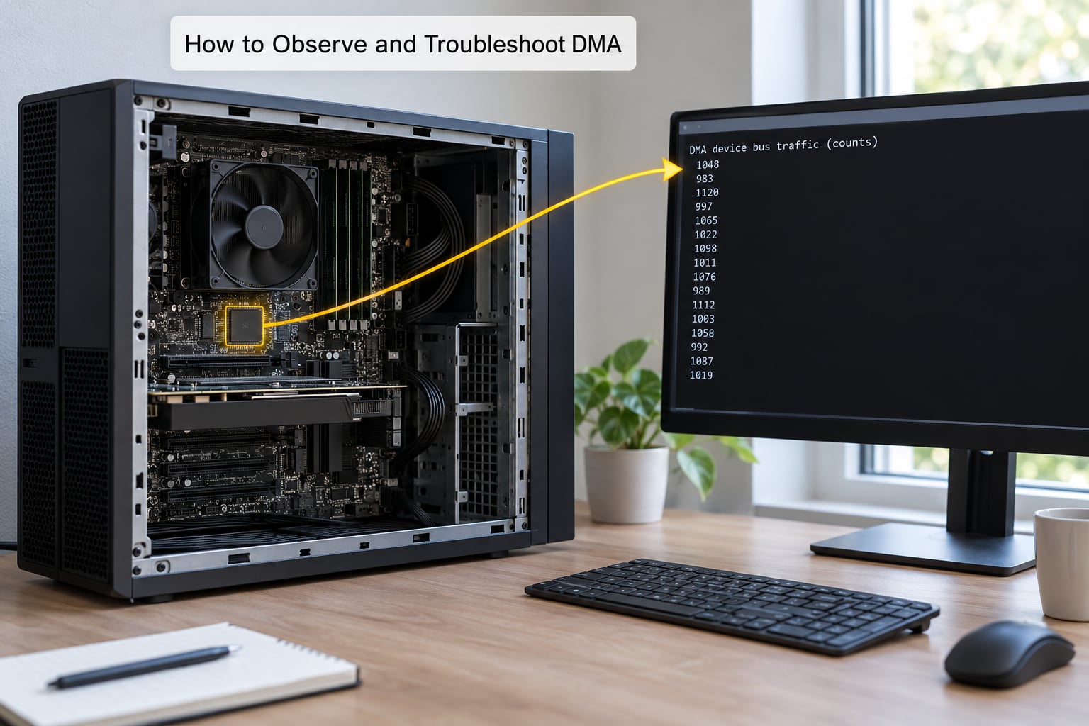
There is no single universal DMA viewer, because the engine lives wherever the vendor put it. What you can do is check the platform-level facts, and on Linux those are all readable from the command line.
On Linux, confirm the IOMMU is actually running before you trust anything else:
dmesg | grep -i -e DMAR -e IOMMUshows whether the IOMMU was initialised, and prints the fault-reporting mode and the registered interrupt.cat /sys/kernel/iommu_groups/lists the groups. One device per group is the clean setup; a group holding several functions means those devices can reach each other’s memory.lspci -v -s <device>and read the DMA lines to confirm the device actually claims bus mastering and is not behind an IOMMU with translation disabled.
On Windows, the equivalents are the System Information page under DMA protection status, the BIOS setting labelled VT-d, IOMMU, or AMD-Vi depending on the vendor, and Device Manager’s DMA protection column for a specific device.
For actual transfer failures, work from symptoms. No completion interrupt points at the request line being masked, a wrong channel number, or an IOMMU fault that stalled the engine. Data arrives but is stale points at cache maintenance. The first bytes are fine and the last ones are garbage points at alignment or a byte-count versus beat-count mismatch. A transfer that works until the machine gets busy points at an unmapped or over-committed buffer.
Two habits save most of this time. Record the address, length, and direction you programmed rather than trusting your memory, and after a failure read the engine’s status register before clearing anything.
Frequently Asked Questions
What does DMA mean in OS?
In an operating system, Direct Memory Access is the path that lets a device move data into or out of a buffer without the CPU copying it. The driver still does the setup: it allocates the buffer, programs the controller, and hands over a physical address range. Completion arrives as an interrupt, and the driver then wakes whatever was waiting on the buffer. IOMMU translation sits on top of this on most modern systems.
What is direct memory access?
Direct Memory Access is a hardware mechanism that lets peripheral devices and I/O controllers read from and write to system memory directly, without the CPU copying every byte. The CPU or its driver programs a controller with an address, a length, and a direction, then steps aside. The controller moves the data on its own and raises an interrupt when it finishes, which frees the processor for other work.
What is the structure of DMA?
A DMA setup has six moving parts: the source device, its request line, the DMA controller or bus master, the system bus, the destination buffer, and the completion interrupt. Inside the controller sit an address generator, a transfer count register, and a control register holding direction and mode. Modern designs replace those registers with descriptors in memory that carry an address, a length, and a pointer to the next descriptor.
What are the disadvantages of DMA?
The main costs are complexity and failure modes. Setup takes microseconds, so tiny transfers are slower than a CPU copy. Buffers must be pinned, which starves the page allocator. Stale cache lines cause silent data corruption if the driver skips cache maintenance. Misalignment and byte-count mismatches truncate transfers quietly. Devices also contend for the bus, and a device that can DMA is a security boundary you now have to police with an IOMMU.
Does DMA mean the CPU is completely bypassed?
No, and this is the most common misconception. The CPU, or the driver running on it, allocates the buffer, pins the pages, programs the address and count, and unmasks the request line. Only then does the controller move data without further CPU involvement. With an IOMMU present, the CPU also decides which physical pages the device is allowed to touch. The CPU steps aside during the transfer, not before it.
Should I disable DMA in my BIOS?
No. Disabling DMA breaks storage transfers, networking, audio, and virtual machine device assignment, so you trade a theoretical risk for a machine that barely works. The better move is to keep DMA enabled and turn on the IOMMU, known as VT-d on Intel and AMD-Vi on AMD, then confirm the device is confined to an isolated group. On Windows, check kernel DMA protection in System Information instead.
Conclusion: Start with the Transfer Path
If you remember one thing, make it the three phases. Somebody programs the controller, the controller moves the bytes while the CPU does something else, and an interrupt brings the CPU back. Everything else, from cycle stealing to scatter-gather to IOMMU groups, is a variation on that path.
When you are learning or debugging, start there rather than in the datasheet. Trace one transfer end to end and name each piece: buffer, descriptor, request line, address generator, count, interrupt. Once you can point at those six things on a real system, the mode bits and the register offsets stop being mysterious.
If you want to go one level deeper first, pick the closest problem. Cache coherency for stale reads, IOMMU groups for virtualisation failures, buffer ownership for intermittent corruption. Narrow problems are much faster than trying to master the whole subsystem at once.