How drivers talk to hardware, explained plainly: a device driver is the software that sits between the operating system and a physical device, turning a generic request like “read 4096 bytes” or “turn this LED on” into the exact register writes, bus transactions and transfer setup that the hardware understands, then turning the hardware’s answer back into a result the rest of the system can use.
That is the whole job. Everything else — the files, the frameworks, the model numbers, the years of bug reports — is plumbing wrapped around that translation step.
This guide traces the full path from an application call to a hardware action, works through a real register-level example, and finishes with the commands you can run on a live Linux or Windows machine to watch the conversation yourself. No vendor documentation required to start, though by the end you’ll see why you eventually need it.
Table of Contents
- What Does It Mean for a Driver to Talk to Hardware?
- Drivers vs applications, in one sentence each
- The Request Path: From Application Call to Hardware Action
- The 5-step lifecycle every driver goes through
- Who controls each step
- How Drivers Communicate With Devices
- Memory-mapped I/O (MMIO)
- Port-mapped I/O
- DMA — direct memory access
- Interrupts and polled I/O
- Comparison of the main mechanisms
- How Drivers Talk to Hardware: A Simple Register-Level Example
- Why a device register is not normal memory
- Interrupts, DMA, and the Operating System
- How a device signals the CPU
- What DMA changes for the driver
- Where the OS steps in: errors, timeouts and cancellation
- A Step-by-Step Keyboard Read Example
- Why Driver Communication Sometimes Fails
- How to Inspect Driver and Hardware Communication
- On Linux
- On Windows
- What you cannot easily observe
- Frequently Asked Questions
- Do drivers access hardware directly?
- What is the difference between firmware and a driver?
- What does a device tree actually describe?
- Why does hardware need documentation so badly?
- Does every device use interrupts and DMA?
- Why do crashes blamed on drivers show no error message?
- Conclusion: Start With the Interface Between Layers
What Does It Mean for a Driver to Talk to Hardware?
A driver talks to hardware the same way you’d talk to someone who only understands one language. The operating system wants to say “read a block of data”; the disk controller only understands “set this register, set that register, start the transfer, tell me when you are finished.” The driver is the translator standing between them.
Without it, every program that touched a disk would need to know that model’s register layout and command timing. Two different SSDs from two different vendors would need different versions of every file-reading program in existence. That’s the problem device drivers exist to solve, and it’s why the operating system exposes one uniform set of I/O operations to applications while the hardware underneath stays wildly inconsistent.
Drivers vs applications, in one sentence each
An application asks for a result — “open this file, send these 900 bytes over the network.” A driver does the work of producing that result by writing to specific addresses in the CPU’s address space or in the I/O port range.
The key mental model: applications run in user mode (ring 3 on x86) and cannot touch hardware registers directly. Drivers run in kernel mode (ring 0) where the CPU will let them perform privileged instructions. The operating system kernel is the referee in between — it validates the request, hands it to the right driver, and keeps user code from crashing the machine.
That protection is not theoretical. A bad read or write in an application gets the process killed. The same mistake in a kernel driver takes down the whole machine with a Blue Screen or a Linux kernel panic. This asymmetry is why a great deal of modern driver work is about doing the dangerous part as small and as short-lived as possible.
Worth stating plainly: the driver does not “run on the hardware” and it is not the firmware inside the device. It’s ordinary compiled code — a Windows .sys file, a Linux .ko module, a macOS kext — that executes on the CPU and issues the bus cycles the device responds to.
The Request Path: From Application Call to Hardware Action
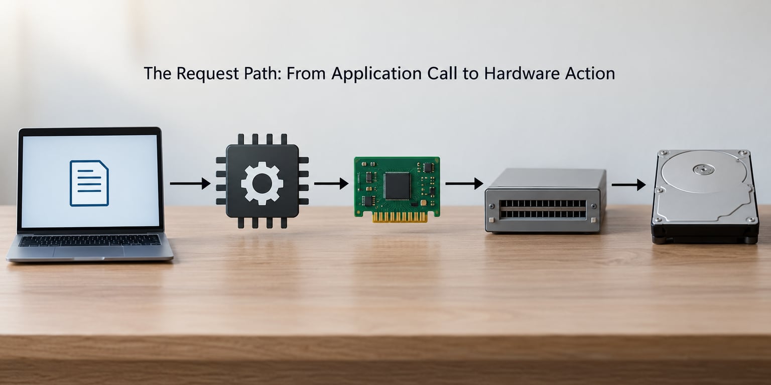
Here’s the chain end to end, using a Linux example where a program writes a command to a device exposed as a file. I’ll walk the same path again for a keyboard later, because keyboards invert part of the flow.
The 5-step lifecycle every driver goes through
1. Enumeration. At boot or hot-plug, the bus controller reads identifying data from the device. On PCIe that’s the vendor ID, device ID, subsystem vendor ID and subsystem ID, plus the class code, stored in PCI configuration space. On USB it’s the device descriptor. The OS matches those numbers against its driver database and picks a driver.
2. Load and initialize. The driver module loads into the kernel. It registers itself with a subsystem (netdev, scsi, alsa, hid, drm), allocates resources, and usually creates a device node such as /dev/ttyUSB0 or a device object visible in the Windows registry. Until this step, the hardware is a powered-off box nothing can talk to.
3. I/O request. The program opens the device node and issues a call. In Linux that’s read(), write(), or ioctl() — the last one meaning “device control”, a syscall carrying a command number and a buffer. In Windows the equivalents are ReadFile, WriteFile and DeviceIoControl, which takes an I/O control code. A Windows driver exposes its kernel surface as a set of IOCTL codes, and a single unchecked length on the buffer behind one is a classic vulnerability class.
4. Hardware action. The driver turns that request into device-specific operations: writes to memory-mapped registers, reads and writes to I/O ports, or programs a DMA engine with a memory address and a length.
5. Interrupt and completion. The device raises an interrupt when it has data or has finished. The driver’s handler runs, reads the result, copies data back, and completes the pending request so the blocked application wakes up.
Who controls each step
The application controls when it wants something. The kernel controls routing, permissions and validation. The driver controls the translation. The device controller controls the bus timing and the protocol on the wire. The device itself controls when work is done and when to signal completion.
If any layer guesses wrong — wrong register address, wrong polarity, missing barrier between writes — the failure shows up somewhere else entirely. That’s why debugging driver problems is mostly about knowing which layer lied to you.
How Drivers Communicate With Devices
There are only a handful of ways a driver can actually touch a device, and once you know which one your hardware uses, most datasheet sections stop being intimidating.
Memory-mapped I/O (MMIO)
The device exposes a window of addresses inside the CPU’s physical address space. Reading from that window returns a device register instead of RAM contents; writing to it changes a device setting. The Linux kernel documentation calls MMIO “the most widely supported form of IO”.
On PCIe, the size and location of each window is advertised in a Base Address Register, or BAR, inside the device’s configuration space. The driver reads the BAR, maps the region into kernel virtual memory, and then reads and writes it with ordinary pointer syntax. Because it uses the same load and store instructions as normal memory, MMIO is fast and needs no special hardware support on the CPU side.
The catch: those loads and stores are not ordered like memory accesses. The CPU can reorder them, buffer them, or merge them. Drivers must use the right memory barriers around register accesses, or a write that was supposed to land before another write may land after it. This is the single most common source of “works sometimes” hardware bugs.
Port-mapped I/O
Older and simpler: the CPU has a separate address space, the I/O port space, with its own instructions (in and out on x86). Reading port 0x60 on a PC’s keyboard controller is how the original IBM PC polled keys. Peripheral chips like the 8250 UART and many legacy parallel and serial controllers were designed around this.
It still shows up constantly, and the distinction is not academic. Run lspci on a machine with an old serial card and you’ll find I/O port resources listed separately from memory ranges in the configuration space.
DMA — direct memory access
When the CPU shouldn’t copy every byte, it hands the job to the device. The driver allocates a buffer, tells the device its physical address and length via registers, and lets the controller write directly into RAM. A 10 GbE NIC or NVMe SSD would be useless if the CPU had to move every byte through a register one at a time.
On PCIe this is called bus mastering. The catch is that the driver has to manage cache coherency — flushing CPU caches so the device sees current data, and invalidating them after the device has written — and it has to keep the buffer pinned and stable, which complicates swapping and compaction on a busy system.
Interrupts and polled I/O
Most modern devices signal the CPU with MSI-X, a memory write that carries an interrupt vector, rather than the traditional dedicated interrupt line. Some low-latency devices, or ones handling extremely regular work, are polled instead: the driver spins in a tight loop reading a status register. Polling wastes CPU but removes interrupt latency and jitter, which is why it’s common in high-speed network drivers.
USB devices get a mention of their own here. Their drivers don’t write the device’s registers directly. The data travels as packets through the host controller’s driver, which converts everything into memory writes. The device driver sees a pipe of buffers, not hardware addresses. The same is true of storage behind AHCI or NVMe’s much higher-level transport layers.
Comparison of the main mechanisms
| Mechanism | How it works | CPU cost | Complexity | Typical use |
|---|---|---|---|---|
| Memory-mapped I/O | Load/store to addresses mapped over device registers (PCIe BAR) | Low, one access per register | Barrier and cache rules | Most modern PCIe, USB host, SoC peripherals |
| Port-mapped I/O | Separate port address space with in/out instructions | Low, but a separate instruction path | Simple, legacy | Legacy UART, parallel ports, old PC controllers |
| DMA | Device reads or writes RAM directly at an address the driver supplies | Almost none per byte | Coherency, pinning, error handling | Network adapters, storage, capture cards |
| Interrupts | Device signals the CPU, which runs the driver’s handler | Context switch cost per event | Affinity, storms, sharing an IRQ line | Completion notification, input events |
| Polling | Driver repeatedly reads a status register | High, spins a core | Simple logic, no handler needed | Low-latency network paths, some audio |
| Message-based I/O | Command and data travel as packets through a host controller | Moderate | Protocol layers, descriptors | USB, Thunderbolt, virtio |
How Drivers Talk to Hardware: A Simple Register-Level Example
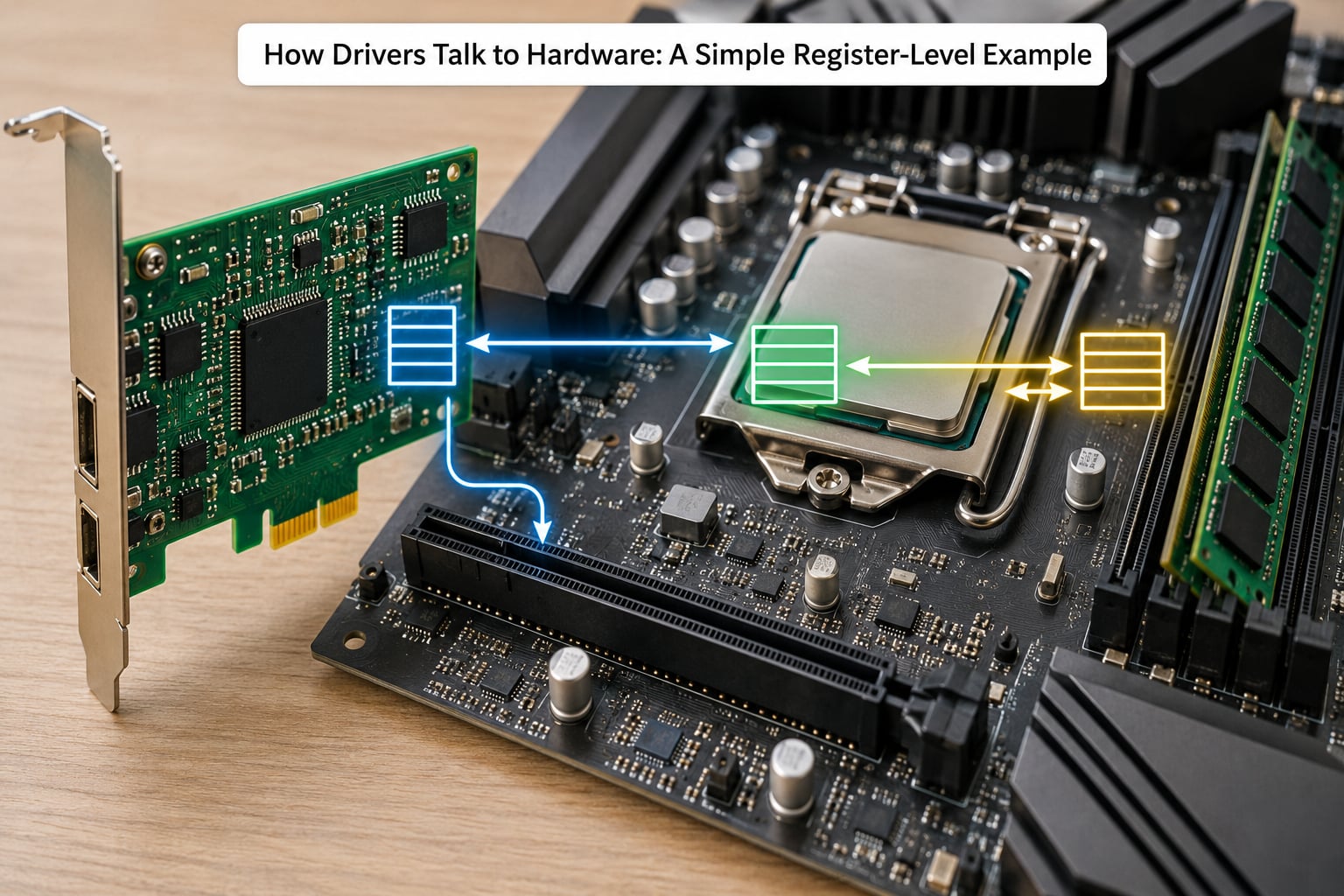
Take a deliberately simple fictional device: a sensor with three registers. A control register that starts a measurement, a status register with a busy bit and a ready bit, and a data register holding the result. Real datasheets look like this, only longer.
/* 1. ask the device to start */
CONTROL = START;              /* write to the mapped address */

/* 2. wait for it to finish */
while ((STATUS & READY) == 0)
    cpu_relax();              /* usually replaced by a real wait */

/* 3. read the answer */
sample = DATA;                /* plain load, but it is a register read */
Three things happened there that explain how drivers talk to hardware better than any definition does. First, the driver wrote to an address that is not RAM. Second, it did not need permission or a syscall — it’s already in kernel mode with the BAR mapped. Third, the wait loop is the simple version; a real driver for anything faster submits work and returns, letting an interrupt come back later.
Why a device register is not normal memory
A load from a device register has side effects. Reading the status register twice might clear an interrupt-pending flag the first time. Reading some FIFO registers pops data. Write ordering is not guaranteed, so a write to a “go” register can be reordered ahead of a preceding configuration write unless a barrier separates them.
That’s why Linux provides readl, writel, readw, writeb and their _relaxed variants instead of encouraging raw pointer dereferencing. The width suffix is the bus width the register expects — 8, 16 or 32 bits — and the accessors insert the barriers where the hardware requires them. A driver written without them may work on one machine and fail on another that orders its writes more strictly.
This is also why a driver author reads the register map section of the datasheet first, before writing any code. The register map, the bit field definitions and the timing requirements are the device’s real API. Source code, header files and driver frameworks are just convenient encodings of that table.
Interrupts, DMA, and the Operating System
Interrupts and DMA are the two mechanisms that make drivers perform rather than just poke, and both bring the operating system into the picture in a specific way.
How a device signals the CPU
When a device needs attention it writes to a designated address — in the case of MSI-X, a special memory region associated with an interrupt vector. The CPU notices, saves its context, and runs the driver’s interrupt service routine, or ISR. The ISR has to be fast, because the interrupt is typically at the same priority as everything else at that level.
So the pattern almost everywhere is split in two: the ISR acknowledges the hardware, reads just enough to know what happened, marks a work queue item, and returns. Deferred work — the actual copying, parsing or protocol handling — happens in a worker thread where a long operation doesn’t block interrupts. Linux deferred work and workqueues, Windows DPCs and IRQLs, macOS thread priorities — different names, same reason.
What DMA changes for the driver
Without DMA, the CPU reads bytes from the device and writes them to memory. With DMA, the device writes memory itself while the CPU does something else. The driver’s job shifts from moving data to describing where the data goes.
Most modern drivers use a ring buffer. The driver owns a circular array of descriptors, each pointing at a buffer and saying how long it is. It hands the device a pointer to the ring, and the device walks it, filling buffers and setting a completion bit. When the device signals, the driver reclaims the completed buffers. Because the ring is a fixed, continuously reused structure, the addresses the device holds stay valid — which is exactly why plain user memory cannot be given to a device without pinning it first.
Where the OS steps in: errors, timeouts and cancellation
Hardware does not always answer. A device can wedge, a DMA transfer can fail with a bus error, an interrupt can be lost entirely. The driver has to convert every one of those into a decision the application can live with, and the operating system gives it the tools to do that.
Timeouts bound the wait. If a read hasn’t completed in a defined interval, the driver gives up, resets or resets-and-retries the device, and returns an error code. Synchronization protects the buffer: locks, atomics and memory barriers keep two CPUs or an interrupt handler and a thread from touching the same descriptor at once. Cancellation handles the case where the application gives up first — closing a file while a transfer is in flight means the driver must stop the engine, not just forget about it, or it will write into memory that’s since been freed.
That last one is why user-mode drivers exist. A UMDF driver on Windows, or a VFIO-based userspace driver on Linux, runs outside the kernel and takes a hardware fault with the process rather than the machine. The cost is a context switch per operation, which is why it’s used for display, printers, sensors and security devices, and rarely for a storage controller.
A Step-by-Step Keyboard Read Example
The keyboard example is worth walking through because the data flows the other direction. Nobody is requesting a key — the hardware has something to say and needs a way to interrupt.
1. The key press. Pressing a key closes a switch matrix contact. The keyboard’s controller detects the change, debounces it, and assigns the position a scan code, a number identifying the physical key rather than the character. That distinction matters: shift and cap-lock later turn the same scan code into a different character, and layout tables turn it into whatever the user’s keyboard language requires.
2. The device raises an interrupt. The keyboard controller (the legacy 8042 on PCs) or the USB host controller in a USB keyboard signals the CPU. The interrupt is registered with the kernel as belonging to the keyboard driver at boot.
3. The driver’s ISR runs. The handler reads the scan code from the device’s data register — one in instruction on port 0x60, or a read from a mapped register over USB. That read both returns the code and, on a legacy controller, acknowledges the pending interrupt. The handler then hands the code to the input subsystem and returns.
4. The input subsystem interprets it. The kernel’s input core keeps the state of modifier keys, resolves the scan code against the active layout, and produces an input event: type, code, value. A letter, a key release, a scrolling wheel notch — all the same three fields.
5. The application receives it. A GUI toolkit or game reads that event stream through an event loop. From the user’s point of view, the character appeared. From the hardware’s point of view, a matrix contact closed and a register was read. Every one of those five steps is a driver, a subsystem or a syscall in between.
The same shape holds for a network card receiving a packet, a USB stick reporting data, or a graphics card needing the CPU to resubmit its command list. The direction of the original request changes, the layers stay the same.
Why Driver Communication Sometimes Fails
Nearly every driver bug is one of a handful of mistakes, and each one leaves evidence if you know where to look.
| Failure mode | What goes wrong | Evidence to check |
|---|---|---|
| Wrong base address | BAR mapped at the wrong offset, so writes land on the wrong register or nothing | Compare mapped ranges against config space output from lspci; reads return all ones |
| Wrong register value or bit field | A bit exists but sits in a different position, or needs a read-modify-write instead of an overwrite | Read back the register after write; compare against the datasheet bit table |
| Missing memory barrier | Two writes get reordered, so the device acts on stale configuration | Failure is intermittent and machine-specific; add readl/writel or explicit barriers and retest |
| Interrupt not firing or misrouted | MSI-X vectors unmapped, IRQ line shared with another device, or the handler never acknowledges | Interrupt counters stuck at zero; two devices assigned the same line; handler logs missing |
| DMA errors and stale caches | Buffers not flushed before the device reads them, or not invalidated after | Corrupted data that changes with cache pressure; check coherency handling in the driver |
| Crossing the user/kernel boundary wrong | An IOCTL buffer length not validated, so the driver reads or writes past the buffer | Unchecked length in the IOCTL path; fault only under load or with a malformed request |
| Timeout without recovery | A wedged device is retried forever instead of reset | Thread stuck in a retry loop; device stays dead until the machine is rebooted |
Note what these have in common: not one of them is a logic error in the sense of a wrong if-statement. They are all assumptions about the hardware that the hardware didn’t share — an address, a bit position, an ordering rule, a timing guarantee. That’s the part beginners find hardest to accept, because the code looks right and reads correctly.
How to Inspect Driver and Hardware Communication
You can watch most of this happening on a machine you already own. The commands differ per platform, so they’re listed separately.
On Linux
lspci -nn lists every PCI device with its vendor, device and class IDs — the numbers a driver is matched against. lspci -vv adds the full configuration space dump, including BAR addresses, assigned I/O ports, IRQ numbers and MSI-X capability entries. lsusb -t does the same job for USB, showing the bus topology and the driver bound to each interface.
lsmod shows loaded modules; modinfo on a module name prints its aliases, which literally list the vendor:device pairs it claims to handle. dmesg (or journalctl -k on systemd systems) is where drivers print their probe results, resource allocations and error codes. Under /sys/bus/pci/devices/, each device directory exposes its config space as readable files, plus iomem_group and resource files showing exactly what ranges the kernel assigned.
To watch register access itself rather than just the surrounding bookkeeping, dynamic debug can turn on the kernel’s debug messages for a specific driver, and ftrace with the mmio or irq events gives you timestamps on the accesses and interrupts themselves.
On Windows
Device Manager is the entry point, but the useful views are underneath it: the Properties dialog’s Details tab shows the driver provider, version, date and the hardware IDs the driver matched. The Resources tab lists the memory ranges and I/O ports assigned to the device, which is the Windows equivalent of reading BAR values. pnputil /enum-devices /class and pnputil /enum-drivers do the same inventory from a shell.
For tracing, Sysinternals’ WinDbg in kernel mode is the real tool — it breaks on driver entry points and lets you single-step I/O reads and writes. The Windows Performance Recorder’s I/O and DPC/ISR analysis shows which drivers are issuing what. And msinfo32 gives a driver inventory with dates, which is how you spot a 2016 network driver still running in 2026.
What you cannot easily observe
Traffic inside a protocol — USB packets, NVMe commands, a network frame’s contents — needs a protocol analyzer or a device that logs internally. Tools like usbmon and BPF programs on Linux, or ETW traces on Windows, get you part of the way. For anything below that, the datasheet and a logic analyzer on the pins are the honest answer, which is exactly why the register map is the primary source and everything else is a convenience.
Frequently Asked Questions
Do drivers access hardware directly?
Kernel-mode drivers do. They run in ring 0 with the privilege to read and write I/O ports and memory-mapped device registers, which is why they can talk to hardware at all. User-mode applications cannot and must not; they go through a system call. The practical split is that a driver issued the access, while the operating system kernel decided whether it was allowed to. Faults in a user-mode driver take down the process; faults in a kernel driver take down the machine.
What is the difference between firmware and a driver?
Firmware is software stored in flash inside the device itself, and it runs on the device’s own processor. A driver is software that runs on the host CPU, inside the operating system kernel or a user-mode host. Firmware can interpret commands, run its own protocol stacks and manage the device’s internals. A driver translates host requests into the operations that firmware exposes through registers. Both are needed, and updating one rarely updates the other.
What does a device tree actually describe?
A device tree is a data structure, not code. It lists the hardware a system has, how it is wired together, which interrupts belong to which device, and what memory ranges each one occupies. Firmware reads it before the operating system loads, and the kernel uses it to match devices to drivers and hand them the right resources, which is how ARM and embedded systems work. On x86 the equivalent job is largely done by PCI configuration space and ACPI tables.
Why does hardware need documentation so badly?
Because a register map is the only description of what the device will actually do. Two devices with identical advertised functions can require completely different register sequences, and the hardware will not tell you when you got the order wrong. Reading a datasheet’s register table, bit field definitions and timing requirements is not a fallback when source code is unavailable; for most low-level hardware it is the primary source, and the headers and frameworks are conveniences built on top of it.
Does every device use interrupts and DMA?
No. Some use both, some use one, and some use neither. A simple GPIO or LED controller is usually polled and needs no DMA. A network card typically uses DMA for data and MSI-X for completion. A USB keyboard arrives as interrupt-driven packets, but the transport is a host controller’s job rather than the keyboard driver’s. Peripheral buses like I2C and SPI have no interrupts at all, so their drivers spin on a status register or rely on a time bound.
Why do crashes blamed on drivers show no error message?
A driver bug that corrupts memory or dereferences a bad address takes the kernel down before any error handler can produce a useful message. The dump that survives is often from a later, innocent-looking line, which is why dump analysis walks the stack and looks for a third-party module frame. Signed drivers, Driver Verifier on Windows and lockdep with KASAN on Linux all add checks that turn silent corruption into a report naming the driver that caused it.
Conclusion: Start With the Interface Between Layers
The one idea worth keeping from all of this: a driver is a translator, and the conversation it conducts is a specific, ordered exchange with a device rather than an abstract “connection” to hardware. Application, system call, kernel, driver, bus transaction, device, interrupt, and back up again — every step has an owner, and the failures cluster at the seams between them.
If you want to go further, work in that order. Find out what bus the device sits on, then find the register map or programming interface the vendor documents. Trace one operation by hand, in a debugger or a driver log, from the system call down to the individual register writes. After that, interrupts and DMA stop being abstract, because you’ll have watched the same mechanism both ways.
And keep in mind that the exact commands, interfaces and register layouts depend entirely on the device and the platform. The structure holds everywhere; the specifics live in the datasheet for that part, on that bus, running that operating system.