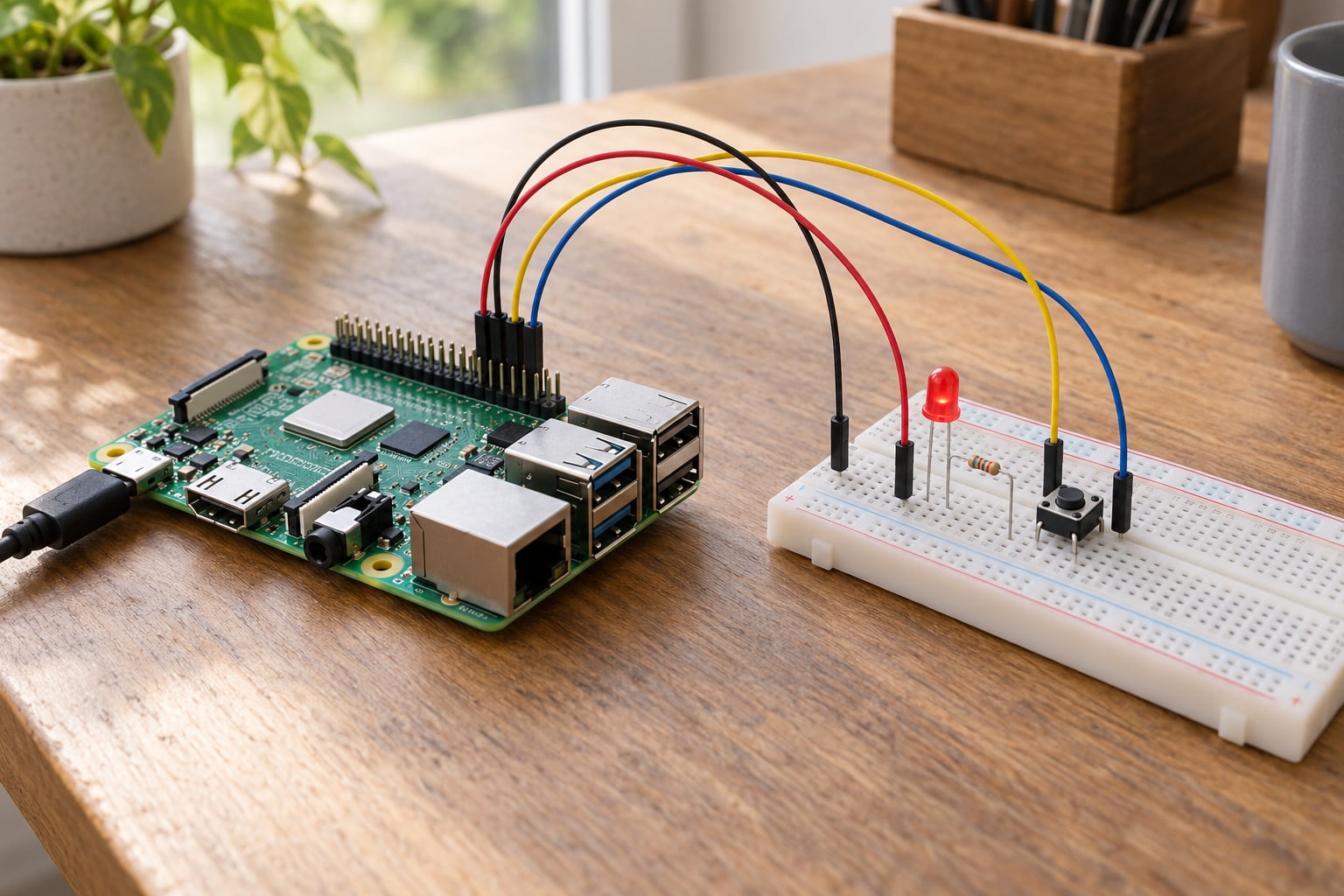
A Raspberry Pi GPIO pin is one of the programmable pins on the board’s 40-pin header, and it exists so software can talk to real electronics. Set a pin as an input and it reports high or low from a button or sensor. Set it as an output and it drives 3.3V or 0V to light an LED, click a relay or fire a stepper motor. That bridge between code and circuitry is the whole point of GPIO.
GPIO stands for general purpose input/output, and on a single-board computer those pins are the difference between a small Linux box that sits on a desk and a controller that reacts to the room it is in. The exact number of usable pins depends on your model, so check the pinout for the board in your hands rather than trusting a diagram from a different one.
Table of Contents
- What Is a Raspberry Pi GPIO Pin Used For?
- How Does GPIO Work on a Raspberry Pi?
- What a Raspberry Pi GPIO pin does in software
- The alternate functions on GPIO pins
- What Can You Connect to a Raspberry Pi GPIO Pin?
- What Is the Difference Between GPIO Input and GPIO Output?
- Which Raspberry Pi GPIO Pins Should Beginners Use?
- How Do You Use a Raspberry Pi GPIO Pin?
- What Safety Rules Apply When Using Raspberry Pi GPIO?
- Frequently Asked Questions
- What is a Raspberry Pi GPIO pin used for?
- Can Raspberry Pi GPIO pins power an LED?
- Are all Raspberry Pi GPIO pins the same?
- Do Raspberry Pi GPIO pins need resistors?
- Can Raspberry Pi GPIO control a 5V device?
- What is the easiest first Raspberry Pi GPIO project?
- Conclusion
What Is a Raspberry Pi GPIO Pin Used For?
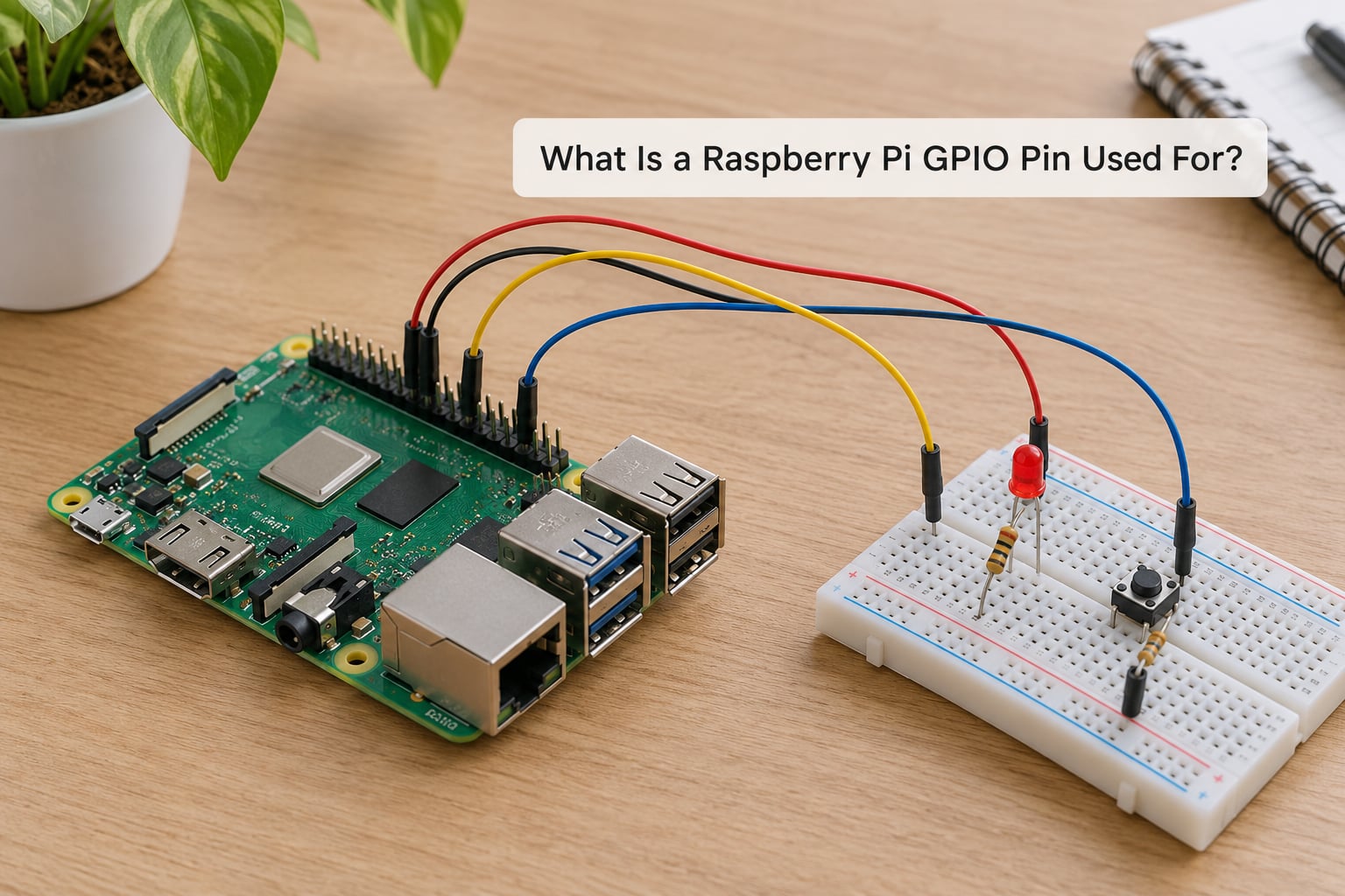
In plain terms, a GPIO pin lets a Raspberry Pi sense the outside world and switch things on and off in it. The same physical pin can do either job, and software decides which one it is doing right now.
Common uses cover a wide range of projects:
- Lighting LEDs as status indicators, or building a whole LED panel or matrix driven row by row.
- Reading push buttons so software can react to a person pressing something.
- Switching relays that control lamps, heaters or solenoids from a safe low-voltage signal.
- Stepping motors and servos, usually through a driver board or transistor since the Pi cannot drive them directly.
- Reading sensors such as PIR motion detectors, reed switches, soil moisture probes and door contacts.
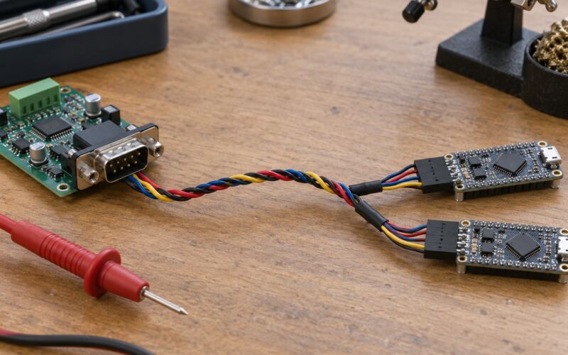
- Speaking serial protocols — I2C, SPI and UART all run on GPIO pins, so displays, sensors and radio modules talk to the Pi over them.
- Producing PWM for motor speed control, LED breathing effects or servo angles.
- Counting and timing events, including pulses from an encoder or a light barrier.
- Handshaking with another microcontroller, such as a Pico, over a couple of pins.
- Bit-banged or hardware-assisted buses where an HAT or breakout would otherwise be needed.
Every one of those jobs is digital. A GPIO pin is one bit at any moment, high or low, and there is no in-between.
How Does GPIO Work on a Raspberry Pi?
GPIO is a programmable interface between software and electronics. The processor can only work in zeroes and ones, so the pin converts between that and voltage: a logic high on a Raspberry Pi GPIO pin puts roughly 3.3V on the pin, and a logic low puts roughly 0V on it.
What a Raspberry Pi GPIO pin does in software
Before a pin does anything useful, software has to configure it. You pick the direction, input or output, set an initial level, and decide whether any pull resistor is enabled. Only then does the pin start behaving the way your program expects.
An output pin is driven by the SoC. You write a 1 and it drives the pin high; you write a 0 and it drives it low. An input pin does the opposite: the outside circuit decides the voltage, and your program reads back whether the pin sees a high or a low.
Because GPIO is digital only, the Pi has no built-in way to read an analog voltage. That catches people out with potentiometers and analog temperature probes. An external ADC board on the SPI or I2C pins is the usual answer.
The alternate functions on GPIO pins
Most GPIO pins can be reassigned to hardware peripherals, which is why one pin can be plain digital I/O on Monday and part of a bus on Tuesday. These alternate functions are pinned to specific GPIO numbers and cannot be moved.
- I2C — two shared wires, SDA and SCL, carrying many devices on the same bus with their own addresses.
- SPI — faster than I2C with separate lines per device, which means more pins but no addressing.
- UART — a serial link with a transmit and a receive line, the traditional way to attach a GPS module or an Arduino.
- PWM — pulse-width modulation, where the pin switches fast and the duty cycle sets an average level.
Pinout diagrams list these in brackets next to the GPIO number, which answers the common forum question about whether any pin can send a signal. Yes, generally — but if the bracket names a function, that pin is already spoken for by that peripheral.
What Can You Connect to a Raspberry Pi GPIO Pin?
Think in two groups. Some components feed a signal into a pin and let the Pi read it. Others take a signal from the pin and need real current to work.
Things you read: tactile push buttons, toggle and reed switches, PIR motion sensors, door contacts, Hall effect sensors, reed switches on a bicycle wheel, and the output of another logic chip. Most of these are open-collector or open-drain devices that pull the pin to ground when triggered, which is why the internal pull-up matters.
Things you drive: a single LED through a current limiting resistor, a string of LEDs, a relay module, a transistor acting as an electronic switch, a servo or stepper through a driver board, or a 7-segment display. Anything drawing more than a pin should supply goes through one of those intermediate stages.
There is also a serial group: LCD and OLED displays, temperature and pressure sensors, ADC boards, and radio modules all connect over I2C or SPI, using the pins listed for those functions.
What Is the Difference Between GPIO Input and GPIO Output?
Input mode makes the pin listen; output mode makes it speak. The table below sets the two side by side.
| Aspect | GPIO input | GPIO output |
|---|---|---|
| Who sets the voltage | The connected circuit | The Raspberry Pi |
| Software action | Read high or low | Write high or low |
| Typical voltage seen | 0V or 3.3V logic | 0V or 3.3V driven |
| Extra component needed | Often a pull-up or pull-down resistor | A current limiting resistor for LEDs |
| Example project | Door contact that triggers a camera snapshot | Relay that switches a garden pump |
Pull-up and pull-down resistors solve one specific problem. A pin configured as input with nothing attached floats, picking up noise and reading randomly. A pull-up resistor connects the pin to 3.3V through a resistor so it reads high by default; a pull-down connects it to ground so it reads low. A switch then pulls it the other way. Raspberry Pi OS lets you turn the internal pull-ups on or off in software, though external ones work fine too.
There is one more subtlety worth knowing: if the software says a pin is an output but the connected circuit forces it to a different voltage, you get a short. The SoC pushes back and current flows until something gets hot.
Which Raspberry Pi GPIO Pins Should Beginners Use?
Most 40-pin headers follow the same shape, but not every position is a GPIO pin. A typical layout breaks down roughly like this:
- Two 5V pins for USB and other 5V loads.
- Two 3.3V pins, and on the Pi 5 an extra pair further along the header.
- Ground pins scattered down both edges — there are usually eight or so.
- GPIO pins carrying the programmable ones.
- Two ID EEPROM pins on models that have them, reserved for board identification.
Power and ground pins are not GPIO. They supply or sink a fixed voltage, which is useful for powering a sensor, but a program cannot set their direction and they will not read a logic state back.
For a first project, pick a plain GPIO pin such as BCM 17 or BCM 27. Avoid BCM 0 and BCM 1 on newer boards, where they are tied to the boot process and pull-ups on them can stop the Pi starting. Leave BCM 2 and BCM 3 alone if you plan to use I2C, and keep off BCM 14 and 15 if you want the serial console, since the boot log prints there.
Numbering trips up almost everyone. Physical pin numbers count positions along the header; BCM numbers name the SoC GPIO the pin is wired to. Physical pin 11 is BCM 17. Physical pin 12 is BCM 18. Older tutorials often used board numbering, so a tutorial saying pin 17 may mean physical 17, which is BCM 0.
For a Raspberry Pi 4 Model B, Raspberry Pi 5 or Zero 2 W, the 40-pin layout applies. Older 26-pin boards, the Pico and the Pico W do not follow it at all, and some boards ship with an unpopulated header you need to solder to. Check your own board before wiring.
How Do You Use a Raspberry Pi GPIO Pin?
The workflow is the same every time: identify the pin by both numbers, wire it, set its mode in software, then read or write it. Here is the shortest useful version on Raspberry Pi OS.
1. Pick the pin and note both numbers. Write down the physical position and the BCM number. Most libraries want BCM.
2. Wire the circuit with the Pi powered off. For an LED, connect the anode through a 220 to 330 ohm resistor to the GPIO pin, and the cathode to a ground pin. The resistor is not optional.
3. Confirm the pin is low by default. A Pi pin starts as an input, so the LED should stay dark after you boot.
4. Run a short gpiozero script. The officially recommended library wraps the pin in a plain object:
from gpiozero import LED
from time import sleep

led = LED(17)

while True:
    led.on()
    sleep(1)
    led.off()
    sleep(1)
5. Check the result. Run it with python3 blink.py from your desktop or terminal. Stop it with Ctrl+C. If the LED stays dark, work through the fault list below.
Other libraries exist and pick up where gpiozero stops. RPi.GPIO exposes raw pin access and callbacks, which is what you want for precise timing. lgpio is a low-level C library with fast bindings for timing-sensitive work. CircuitPython runs on the Pi but is usually reached for when the same code also has to run on a microcontroller. For a first project, gpiozero is the shortest route to something that works.
If you need to see pin state from another machine, run a server such as pigpio on the Pi and connect from a PC over the network. That approach is common in home automation setups where a web page or phone triggers a pin.
What Safety Rules Apply When Using Raspberry Pi GPIO?
These are the rules that stop boards from dying. Work through them before every power-on.
- Treat every GPIO pin as 3.3V only. The Pi’s GPIO is not 5V tolerant. Feeding 5V into a GPIO input can permanently damage the SoC. Community advice is consistent on this one.
- Level-shift anything above 3.3V. Use a divider or a proper level shifter module. A two-resistor divider works: value the top resistor so the output lands near 3.3V at the pin.
- Connect grounds together. Your circuit and the Pi must share a common ground reference, or readings are meaningless.
- Put a current limiting resistor in series with every LED. An LED without one is a short circuit with a light bulb in it.
- Never drive a motor, relay or mains load from a GPIO pin. Use a transistor, MOSFET or relay module rated for that load, with a flyback diode across inductive parts.
- Power off before rewiring. Hot-swapping jumpers while a pin is driving high is how boards get destroyed.
- Check the documentation for your model. Current budgets and available header pins differ across boards.
That last point covers one common surprise: the documented peripheral current ceiling on the Pi 5 is lower than older boards, and the 5V and 3.3V header pins stop behaving once you exceed what the onboard supply can deliver.
If an LED will not light, check the resistor is in line, confirm the cathode goes to ground, and verify you used the BCM number the script expects. If a pin reads high no matter what, a missing pull-down or a floating wire is usually to blame. If a relay will not click, the coil almost always needs its own supply and a transistor driver.
Frequently Asked Questions
What is a Raspberry Pi GPIO pin used for?
A Raspberry Pi GPIO pin lets software read or write a single digital signal. As an input it reports high or low from a button, switch or sensor; as an output it drives 3.3V or 0V to light an LED, trigger a relay through a driver, or control a servo. It is the bridge that turns a single-board computer into a device that reacts to the physical world.
Can Raspberry Pi GPIO pins power an LED?
Yes, for a single small LED, but always through a current limiting resistor of roughly 220 to 330 ohms. Without the resistor the pin effectively becomes a short circuit. For anything brighter, several LEDs, or a strip, drive the load from the 3.3V or 5V pin through a transistor rather than sourcing the current from the GPIO pin itself.
Are all Raspberry Pi GPIO pins the same?
No. Every GPIO pin handles the same basic digital input and output job, but many also carry fixed alternate functions such as I2C, SPI, UART or PWM. A handful are tied to the boot process or the serial console, and the ID EEPROM pins are not general purpose at all. Power and ground positions on the header are not GPIO either, so check the pinout for your model.
Do Raspberry Pi GPIO pins need resistors?
For LEDs, yes, always. For a button, usually a pull-up or pull-down resistor, either external or the internal ones you enable in software, so the pin does not float and read random values. A divider is needed when a signal exceeds 3.3V. GPIO outputs can only supply a small amount of current, so anything bigger needs a resistor and a transistor or relay driver.
Can Raspberry Pi GPIO control a 5V device?
Not directly as an input, because Raspberry Pi GPIO pins are not 5V tolerant and 5V can damage them. Use a resistor voltage divider or a level shifter module to bring the signal down to 3.3V. As an output, a GPIO pin can control a 5V relay module indirectly, because the module handles the 5V load itself and only takes a low-current 3.3V trigger from the pin.
What is the easiest first Raspberry Pi GPIO project?
Blink one LED. Wire the anode through a 220 to 330 ohm resistor to a GPIO pin such as BCM 17, and the cathode to ground. A short gpiozero script with LED(17) and a sleep loop is enough to make it blink. It teaches pin identification, direction, current limiting and basic Python control without any risk of a damaged pin.
Conclusion
A Raspberry Pi GPIO pin is used for one thing: turning software into a physical signal, and a physical signal back into software. That covers LEDs, buttons, relays, motors, sensors and the I2C, SPI, UART and PWM buses, all through the same row of pins on the header.
Start with an LED and a resistor, or a button with a pull-up, and get that working before adding anything else. Then check the pinout and voltage figures for your exact model, because that is where nearly every avoidable mistake comes from.