A bootloader on an embedded device is a small program stored in a protected area of non-volatile memory that runs the moment the chip is reset or powered on. It does the minimum hardware setup needed to talk to flash, decides which firmware image to run, and then hands control over to that firmware. Everything after it — the RTOS kernel, Linux, your application — is useless until the bootloader has done its part.
This guide walks through the boot sequence on a microcontroller, clears up the bootloader/startup-code/firmware confusion that trips up most newcomers, and finishes with the checks to run when a board that used to work suddenly won’t start.
Table of Contents
- What Is a Bootloader on an Embedded Device?
- Why Does an Embedded Device Need a Bootloader?
- How Does an Embedded Bootloader Work?
- What Is the Difference Between Bootloader, Firmware, and OS?
- What Kinds of Bootloaders Are Used on Embedded Devices?
- How Does a Bootloader on an Embedded Device Differ from a PC Bootloader?
- What Happens During an Embedded Device Boot Failure?
- How Do You Inspect or Update an Embedded Bootloader?
- Confirm the bootloader actually ran
- Find it in the memory map
- Read the boot log
- Use the vendor’s own flashing tool
- Verify what you write
- Frequently Asked Questions
- Is a bootloader the same as firmware?
- Where is the bootloader stored on an embedded device?
- Does a bootloader load the operating system?
- Why does an embedded device enter a bootloader loop?
- Can a bootloader update itself?
- How can a developer debug an embedded bootloader?
- What to Do First When an Embedded Device Will Not Boot
What Is a Bootloader on an Embedded Device?
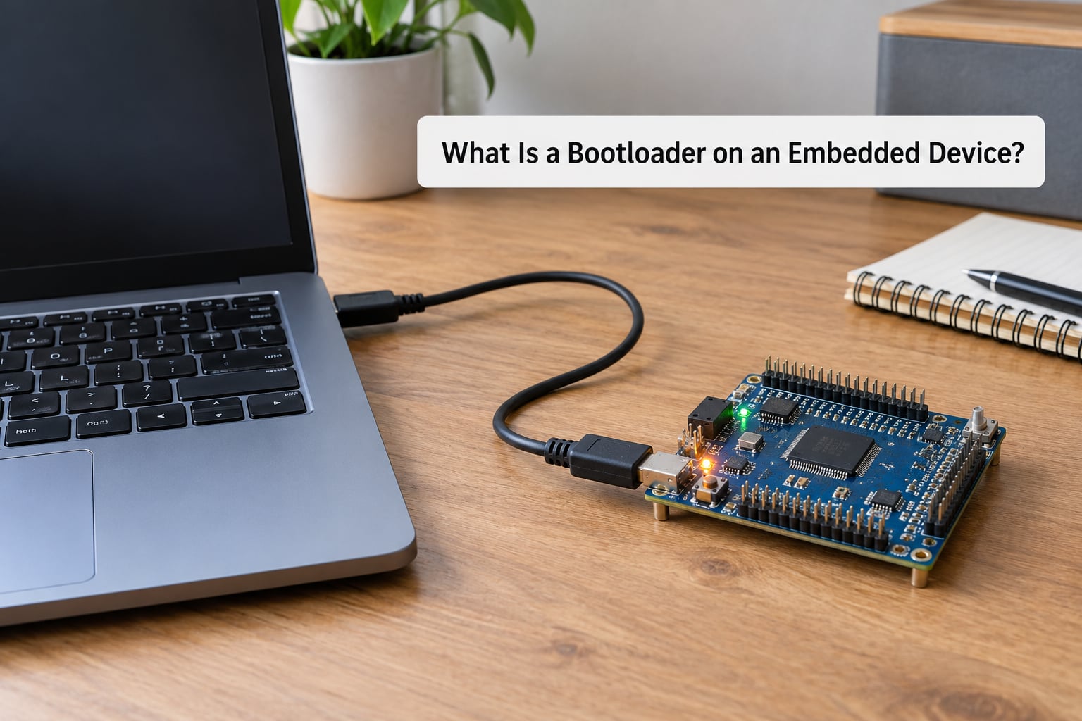
On an embedded device, a bootloader is the first piece of software the processor executes after a reset. It lives in on-chip ROM or in a reserved region of flash, is usually written once at the factory, and its only jobs are to bring the hardware to a known state, pick a firmware image, and jump to it. The word “load” in the name is historical — on a microcontroller the firmware already sits in the same flash the CPU can execute from, so the bootloader mostly decides and verifies rather than copying gigabytes around.
The cleanest way to picture it: the bootloader is a gatekeeper standing between raw silicon and your code. If it decides the firmware is bad, it can hold the device in a recovery state or listen for a new image instead of starting the application.
One thing to clear up early. The bootloader is not the same as firmware, the operating system, or the C startup code. It is the thing that runs before all of those, and it stays resident while the application runs.
Why Does an Embedded Device Need a Bootloader?
Flash memory is self-programmable, which is the whole reason bootloaders exist. Earlier parts stored code in EPROM that had to be physically removed and UV-erasable to change, so updating a device meant a technician and a chip puller. Once internal flash with an on-chip charge pump arrived, the device could rewrite its own code. That created a new problem: something has to decide when a rewrite is safe.
A bootloader solves the startup problems that come with that freedom:
- Bringing up the hardware. Clocks, flash wait states, GPIO defaults, and on bigger parts the DDR controller have to be configured before anything else can run.
- Choosing what to run. Reading stored metadata to decide between two firmware slots, an SD card image, a USB host, or a recovery application.
- Deciding what counts as valid. Checking a signature, a checksum, or a version counter before handing over control.
- Receiving new firmware. Accepting an image over USB, UART, SPI, CAN, Ethernet or Wi-Fi, so a field update never needs a JTAG programmer.
- Failing safely. If nothing valid exists, stay in the bootloader and wait instead of jumping into empty flash and resetting forever.
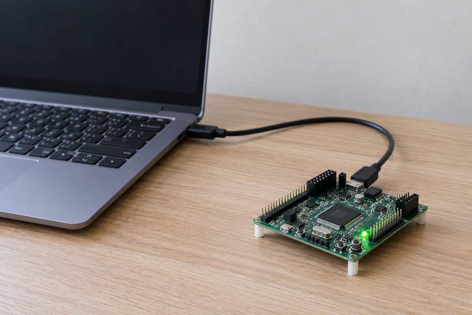
On developer boards you see the vendor’s version of this for free. Microcontrollers such as the ATmega328P and STM32 families ship with a ROM or system bootloader that listens on serial or USB, which is why you can flash a fresh board over a USB cable with nothing else plugged in.
How Does an Embedded Bootloader Work?
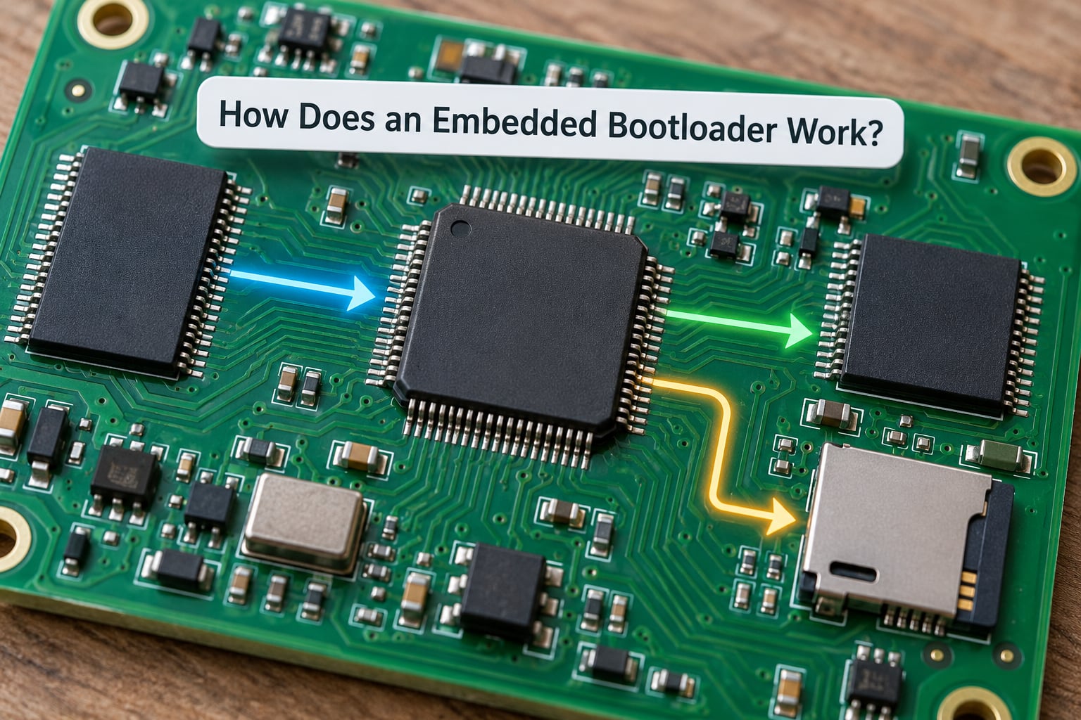
The normal path is short and boring, which is exactly what you want. On an MCU it usually looks like this:
- Reset. Power is applied or the reset pin goes low. Every architectural exception level is masked and the processor fetches from the reset vector, a fixed address at the top of boot ROM on most parts.
- Boot ROM. Immutable silicon or mask ROM code runs. It sets up clocks, initializes memory, and copies or jumps into flash-resident bootloader code.
- First-stage bootloader (FSBL). The minimum code needed to talk to storage. On a Linux SoC this stage also brings up DRAM before anything else can run, because the kernel image lives in external memory.
- Second-stage bootloader (SSBL). A fuller loader with drivers, a command line, environment variables and update logic. On MCU boards this stage is often skipped and the FSBL does the whole job.
- Kernel, RTOS or application. The bootloader loads or validates the image, sets boot parameters — a kernel command line, a device tree, stack pointer — and jumps to the entry point.
Jumping is the part beginners get wrong. The bootloader does not “run” the application; it sets up registers and memory, then transfers control. On ARM that’s a branch to the reset handler with the vector table base in the right register. Nothing returns unless the application deliberately jumps back — which is exactly what a firmware update request does.
On an embedded Linux board the chain is longer: SoC boot ROM, then FSBL, then U-Boot, then kernel, then init and the rest of user space. A device tree usually tells the bootloader which memory regions exist and which storage device holds the root filesystem.
What Is the Difference Between Bootloader, Firmware, and OS?
This is the single most repeated question on embedded forums, and the confusion comes from people using “firmware” for everything. Here is the practical split.
| Component | What it does | When it runs | Size |
|---|---|---|---|
| Boot ROM | Fixed reset handling and clock setup in silicon or mask ROM | First, always | Few KB, not editable |
| Bootloader | Picks and verifies the image, accepts updates, recovery | Right after boot ROM | 2 KB to a few hundred KB |
| Startup code / C runtime | Sets up stacks, clears .bss, copies .data, calls main | Once per boot, after the bootloader | A few KB, usually part of the application image |
| Application firmware | Your product logic | Main program | KB to MB |
| RTOS kernel | Scheduling, tasks, synchronisation | After the bootloader hands over | 10s of KB up |
| OS and user space | Processes, filesystems, services | After the kernel | MB |
The startup-code row is the one to remember. Startup code makes memory look like C expects it to. A bootloader makes a decision about what should be running. Startup code is written by your compiler toolchain; the bootloader is written by a human or a vendor and lives at a fixed, reserved address.
What Kinds of Bootloaders Are Used on Embedded Devices?
The vocabulary is inconsistent across vendors, so match terms to what the chip actually does rather than to the label.
- ROM-resident. Masked into the chip or burned into a small internal ROM. Permanent and tamper-resistant, common on cost-sensitive parts and on most secure boot chains.
- Flash-resident. Stored in a reserved sector of internal flash, protected by boot fuses. This is what most MCU boards ship with, and what you replace when you install your own loader.
- First- and second-stage. Standard on application processors. FSBL does the impossible job — DRAM init and flash access. SSBL adds drivers, networking for downloads, and a shell.
- MCU ISP / serial loaders. Small loaders inside the chip that accept firmware over a serial or USB protocol. On STM32 parts this is the built-in system bootloader; on ATmega parts it’s the optiboot family.
- U-Boot and das U-Boot. The dominant embedded Linux bootloader, a full environment with a command shell, memory probing, boot delay and network or USB update. das U-Boot is a maintained fork and the default choice on most current SoCs.
- Barebox. A smaller, leaner alternative to U-Boot that still gives you a shell and drivers, used where flash and RAM budget matter.
- FPGA bitstream loaders. On FPGA-based systems the bootloader’s job widens: it may configure the fabric, load the bitstream over JTAG or from flash, and then coordinate which soft-core firmware and OS run alongside it.
A microcontroller bootloader and an embedded Linux bootloader share the same idea but not the same scale. One loads a 40 KB image from the same flash it executes from; the other loads a kernel into external DRAM and hands over a device tree and a whole root filesystem.
How Does a Bootloader on an Embedded Device Differ from a PC Bootloader?
Most confusion here comes from arriving from BIOS and UEFI articles. The concepts rhyme, the engineering does not.
Hardware control. A PC bootloader talks to well-documented, standardised hardware. An embedded bootloader is often the only code that knows how the DDR pins, flash bus or a custom PMIC are wired.
Storage assumptions. U-Boot is normal on embedded Linux boards because boot media are diverse — SD, eMMC, NAND, network. MCU bootloaders usually assume one internal flash.
Update mechanism. The embedded case is the whole point: updates arrive over the air through a bootloader that is already running, with no programmer and no disassembly.
Timing. A boot delay of two seconds costs nothing on a server and is unacceptable on a motor controller, an alarm panel or a medical pump. Embedded bootloaders are built to be as short and deterministic as the power budget allows.
Debugging. Desktop boot problems are fixed with a USB keyboard and a monitor. Embedded ones are usually found with a serial console, a debugger probe, or by reading a memory map. Boot pins and fuses that you cannot reach without a programmer mean a mistake can be permanent.
That last point is why forum readers are rightly cautious about bootloader experiments. Flashing a wrong offset on a dev board is a bad afternoon; blowing a one-time-programmable lock fuse on a production part is a dead part.
What Happens During an Embedded Device Boot Failure?
A boot failure is nearly always one of a handful of things. Match the symptom to the row and you usually have your next move.
| Symptom | Likely cause | What to check |
|---|---|---|
| Board resets in a loop, no serial output | Application never reaches its init code | Attach the serial console first, then the debugger |
| Stops at the bootloader prompt | No valid image, or update failed partway | Check the image version/signature metadata and re-send it |
| Works after power cycle, fails after a failed update | Power lost mid-write, slot corrupted | Use the recovery slot and fix the update ordering |
| Runs firmware built for the wrong memory layout | Wrong linker script, image loaded at the wrong offset | Compare the linker script against the actual flash map |
| Peripherals dead but CPU running | Clock, pin mux or peripheral init skipped | Check whether startup code ran before peripheral setup |
| Nothing at all, no LED, no current draw spike pattern | Boot pins or fuses set wrong, hardware fault | Check strap pins, then the datasheet’s boot mode table |
Watchdog resets deserve their own note. Many MCUs leave the watchdog running through the bootloader, and if the bootloader takes too long — say, waiting on a USB host that isn’t there — the watchdog fires and you get a repeating reset with no clue why. Disabling or feeding the watchdog early in the bootloader is routine.
How Do You Inspect or Update an Embedded Bootloader?
This is where the theory turns into practice on your own board. The exact steps are always chip-specific, so take the menu names from the vendor’s reference manual rather than from a blog, including this one.
Confirm the bootloader actually ran
Open a serial console at the baud rate the board’s documentation states and reset the device. A working bootloader prints a version banner or a short prompt before handing over. Silence means the loader was skipped or never started.
Find it in the memory map
Open the linker script for your project and look for the reserved region at the bottom of flash — commonly address zero on ARM, or the boot section on AVR. Your application code should start after that region with a matching gap. If the linker script has no gap, you have overwritten the bootloader.
Read the boot log
On Linux boards, interrupt the boot with a key during the boot delay and inspect U-Boot’s environment. It will show the detected memory map, storage devices, boot source order and the images it found valid or invalid. This is also where boot timeout values and bootargs live.
Use the vendor’s own flashing tool
Every serious vendor ships a programmer utility with a bootloader-update mode. Use it to read the current loader back before overwriting anything, and keep that backup somewhere safe.
Verify what you write
Compute the checksum or signature your bootloader expects, write the image with the vendor tool, and read it back to confirm. On a device with secure boot, an unsigned or wrongly signed image simply will not run — which is the system working as designed.
Power-cut testing belongs in your schedule too. A bootloader that cannot survive losing power in the middle of an update is a bootloader that will brick a device in the field.
Frequently Asked Questions
Is a bootloader the same as firmware?
No. Firmware is the broad term for the software running on the device, and the bootloader is one specific piece of it. The bootloader lives at a fixed reserved address, runs first at every boot, and its job is to select and verify the firmware image before handing control over. The application firmware does the product work after that.
Where is the bootloader stored on an embedded device?
Usually in on-chip boot ROM, or in a reserved region at the base of internal flash that your linker script keeps clear. On application processors with external memory, the first stage sits in on-chip flash or QSPI because DRAM is not usable yet. You can confirm the address by reading the project’s linker script or memory map.
Does a bootloader load the operating system?
On a microcontroller it usually does not need to. The firmware is already in executable flash, so the bootloader validates it, sets a couple of registers and jumps to the entry point. On embedded Linux it genuinely loads things: it initializes DRAM, brings up storage, reads a device tree and kernel command line, then loads the kernel image and hands over.
Why does an embedded device enter a bootloader loop?
Usually because no image passed validation, so the bootloader stays resident waiting for firmware. A corrupt or partly written slot, a failed signature check, a bad version counter or a locked boot fuse all produce this. If instead the board resets rapidly with no output, the application is crashing early and a watchdog is resetting the chip.
Can a bootloader update itself?
Yes, but it has to stage the update carefully. Common designs keep the running loader code in one flash region, write the new loader into a second region, then flip a marker that says which one is active on the next reset. Self-overwriting in place risks leaving the device with no valid loader at all if power drops mid-write.
How can a developer debug an embedded bootloader?
Start with a serial console and capture the boot output, since most bootloaders print what they attempt and where they stop. Then use a hardware debugger to break at the reset vector and step through the early init. Check the memory map against your linker script, verify the image offset, and read back any image you flashed before assuming the code is wrong.
What to Do First When an Embedded Device Will Not Boot
Confirm power and reset behaviour first, then watch the serial console during a reset. Whatever the bootloader prints tells you which stage it reached, and where the output stops is usually where the problem is.
Next, verify the image and memory layout: check the bootloader’s version metadata, the reserved flash region, and that your image sits at the offset the linker script expects. If all of that lines up, go to the board and chip vendor documentation for the boot mode table and fuse settings.
And if you want to build one yourself, do it on a board you can afford to lose. Writing a bootloader is the fastest way to understand the boot process — and the fastest way to learn why the safety rails exist.